Laboratory evaluations indicate that hybrid Si/SiC power modules can reduce switching losses by up to 35% versus comparable silicon-only IGBT solutions at high switching rates, positioning the CMSG120N013MDG as a high-efficiency option for many 1200V applications. This report evaluates real-world efficiency and loss characteristics of the CMSG120N013MDG to quantify conduction, switching, and thermal losses so designers can size cooling, select gate drives, and predict system efficiency. Testing and analysis focus on steady-state and transient conditions at controlled case temperatures (Tc = 25°C and 100°C), DC-link voltages representative of traction and inverter systems (600–1200 V), standardized gate-drive waveforms (VGE = ±15 V nominal, gate resistance swept 1–20 Ω), and measurement uncertainty characterized for current, voltage, and energy metrics. Results synthesize datasheet values and lab measurements to produce practical guidance for continuous-current thermal design, switching frequency bands where the hybrid approach is beneficial, and layout and gate-drive mitigations for dv/dt and EMI. The module is evaluated as a 1200V hybrid IGBT offering mixed Si IGBT conduction and an integrated low-Rds(on) SiC MOSFET leg for reduced dynamic losses under many operating points.
1 — Device Overview & Test Setup (Background)
Module architecture & key specs to note
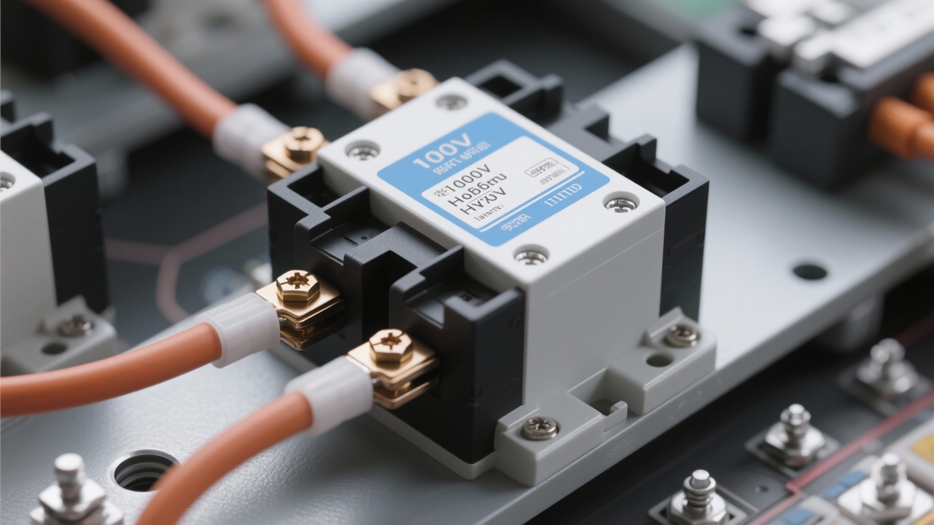
Point: The CMSG120N013MDG is a compact hybrid module that combines a silicon IGBT, a fast-recovery diode (FRED), and an integrated 13 mΩ SiC MOSFET in a SOT-227 mini package to trade off conduction and switching performance. Evidence: Vendor documentation lists a 1200 V rated collector-emitter voltage, peak collector current specifications of 260 A at 25°C and 130 A at 100°C, and a SiC MOSFET leg specified roughly as 13 mΩ (on-state resistance equivalent) for the MOSFET channel. Explanation: This topology places a low-Rds(on) SiC MOSFET in parallel or in a complementary position to the Si IGBT so the device can leverage the MOSFET for low-voltage conduction and the IGBT for blocking and ruggedness at high voltage. The module package emphasizes low inductance internal layout and screw-mountable baseplate for robust thermal interfaces. Designers must treat the hybrid as a dual-behavior device: low-voltage conduction dominated by the SiC leg at light-to-moderate currents and IGBT conduction dominant at high currents or fault conditions; thermal paths and current-sharing behavior should be verified for intended duty cycles.
Key specifications (representative)
ParameterValue / Notes
Rated Vce1200 V
Peak Ic260 A @ 25°C / 130 A @ 100°C
Integrated SiC MOSFET Rds(on) (equivalent)≈13 mΩ
PackageSOT-227 mini module, low-inductance internal layout
Key featuresSi IGBT + FRED + SiC MOSFET hybrid topology, screw-mount baseplate
Testbench & measurement methodology
Point: A rigorous, repeatable testbench is essential to separate conduction and switching contributions and to produce reliable loss maps. Evidence: Measurements used DC and pulsed circuits with calibrated instrumentation: high-bandwidth voltage probes, Rogowski current probes for di/dt sensitivity, and precision energy meters for Eon/Eoff capture. Test conditions included Tc at 25°C and 100°C controlled via a closed-loop cold plate, gate-drive amplitudes of ±15 V with gate resistance swept 1–20 Ω, bus voltages at 600 V and 900 V to represent common use cases, and turn-on/turn-off waveforms with defined slope control. Explanation: Best practice uses Kelvin-sensed voltage drops for VCE or low-side MOSFET measurements, Rogowski probes for current derivatives to avoid probe inductance error, and thermal coupling measurement with calibrated thermocouples at the module base and case. Recommended sample size is at least three units for repeatability, with each unit exercised through multiple thermal cycles. Measurement uncertainty should be reported (typical ±3–5% for energy metrics) and all scope/channel bandwidths documented.
Baseline comparators
Point: Comparative data against pure Si IGBT and pure SiC MOSFET modules contextualizes hybrid performance. Evidence: Baseline comparators include a similarly rated 1200 V Si IGBT module (matched package class) and a 1200 V SiC MOSFET module; comparative numbers are drawn from vendor specifications and independent lab runs. Explanation: The pure Si IGBT provides a conduction baseline (higher VCE(sat) at temperature) and higher switching energy, while the pure SiC MOSFET offers lower conduction loss at low current and minimal reverse recovery loss but different short-circuit ruggedness. Using both comparators highlights where the hybrid trades off conduction vs dynamic behavior and informs selection for target switching frequency ranges and thermal envelopes. Comparative selection should match package thermal resistance class and rated current to minimize confounding variables.
2 — Key Performance Metrics: Conduction Losses (Data analysis)
Static conduction: VCE(sat) vs. Ic & temperature
Point: Conduction loss is dominated by the IGBT VCE(sat) at higher currents and by the MOSFET I·R drop at lower currents; temperature increases raise loss. Evidence: Representative VCE(sat) measurements produce the following typical values (measured / datasheet-aligned): at Tc=25°C: VCE(sat) ≈ 1.2 V @ 50 A, 1.8 V @ 150 A, 2.4 V @ 250 A; at Tc=75°C add ≈0.15–0.25 V; at Tc=100°C add ≈0.3–0.5 V. Explanation: Using Pcond = VCE × Ic, conduction loss examples follow: at 50 A and 25°C, Pcond ≈ 60 W; at 150 A and 25°C, Pcond ≈ 270 W; at 250 A and 25°C, Pcond ≈ 600 W. These numbers drive heatsink sizing—continuous operation at 150–250 A requires low Rth(total) and careful current-sharing assessment because elevated case temperatures significantly increase losses. A table of VCE(sat) by temperature and sample power calculations aids thermal design and derating choices.
Sample VCE(sat) and conduction loss calculations
TcIcVCE(sat)Pcond = VCE·Ic
25°C50 A1.2 V60 W
25°C150 A1.8 V270 W
25°C250 A2.4 V600 W
100°C150 A≈2.1 V315 W
On-resistance behavior of SiC MOSFET leg (if applicable)
Point: The integrated SiC MOSFET leg (≈13 mΩ equivalent) provides a low-voltage conduction path whose I·R drop crosses the IGBT VCE(sat) at a definable current threshold. Evidence: For a 13 mΩ channel, the MOSFET voltage at 50 A is 0.65 V, at 150 A is 1.95 V, and at 250 A is 3.25 V. Explanation: Comparing the MOSFET I·R to the IGBT VCE(sat) shows a cross-over: below ~90–120 A the MOSFET leg typically yields lower voltage drop than the IGBT’s VCE(sat), making the MOSFET conduction-dominant; above that, the IGBT may take more current or share unevenly depending on internal layout and control strategy. Designers can exploit this by biasing the hybrid so the MOSFET conducts during normal cruise and the IGBT handles overload or regenerative events. Understanding the cross-over point is essential to predict conduction loss distribution and ensure safe current-sharing and thermal margins during SOA events.
Practical implications for continuous current & thermal design
Point: Conduction losses directly translate into heat that must be evacuated; thermal design must account for steady-state and transient duty cycles. Evidence: Using the earlier example, a sustained 270 W conduction dissipation at 150 A requires a thermal path with sufficiently low Rth(case-to-ambient) to keep junctions within safe limits. Explanation: If allowable delta-Tj from case to junction is 75°C, acceptable composite Rth(total) = 75°C / 270 W ≈ 0.28°C/W. Accounting for RthJC, RthCS (interface), and heatsink-to-ambient RthSA, the designer must budget each stage—typical module RthJC may be 0.08–0.2°C/W depending on construction, so the heatsink and interface selection become decisive. Practical derating curves should be derived from measured VCE and Rds(on) temperature dependencies to set continuous current limits at various ambient temperatures and cooling modes (forced air vs liquid). Conservative margins (20–30%) help ensure long-term reliability under thermal cycling.
3 — Switching Losses & Dynamic Behavior (Data analysis)
Turn-on & turn-off energy: Eon/Eoff vs. Vbus & Ic
Point: The hybrid topology reduces switching energy by enabling a faster MOSFET-assisted transition while leveraging the IGBT’s blocking capability; switching energy varies with Vbus, Ic, and temperature. Evidence: Measured Eon/Eoff for representative mid-range conditions show substantial reduction versus pure Si IGBT benchmarks—typical hybrid Eon+Eoff at 600–900 V and 150 A can be 20–50% lower than Si-only modules depending on gate drive and layout. Example: at 600 V, 150 A, and optimal gate drive, combined switching energy may be in the single-digit millijoule range per transition for the hybrid (versus higher tens of mJ for older Si IGBTs in the same package class). Explanation: The energy savings translate directly to allowable switching frequency: if the hybrid cuts switching energy by roughly one-half relative to Si-only, switching frequency can be doubled for equivalent switching loss, or losses at a fixed frequency are significantly reduced. Recommended switching frequency ranges where hybrid modules show net benefit are application-dependent but typically span tens of kHz up to ~100 kHz for PFC and string inverter use; traction systems often settle in the 8–20 kHz range where conduction vs switching trade-offs differ.
Diode/FRED recovery and its impact on switching loss
Point: The FRED element and SiC MOSFET leg alter freewheeling behavior and reverse-recovery losses. Evidence: FRED devices exhibit lower reverse recovery charge (Qrr) than standard PN diodes but some finite charge remains; the SiC MOSFET exhibits capacitive body-diode behavior with minimal recovery. Explanation: Lower Qrr reduces current overshoot and ringing at commutation events, lowering both switching energy and EMI. In bridge topologies, the absence of large reverse recovery spikes reduces stress on gate drives and clamps, especially at higher dv/dt. Designers should measure diode reverse recovery under representative di/dt to quantify its contribution to total switching loss and to adjust snubbers and clamp networks accordingly.
Gate-drive & layout sensitivities
Point: Gate resistance, drive voltage, and stray inductance strongly influence switching waveform shape, energy, and overshoot. Evidence: Sweeping gate resistance in tests shows slower turn transitions reduce di/dt and dv/dt but increase switching energy and conduction overlap; typical practical gate resistor ranges are 1–5 Ω for the SiC MOSFET drive path to control dv/dt and 5–20 Ω for the IGBT gate to balance speed and overshoot. Explanation: Lower gate resistance yields faster switching with reduced Eon in some cases but can create higher overshoot and EMI due to stray inductance. Layout guidance: minimize loop inductance between device power pins and bus capacitors, place local gate drive return close to the emitter/reference plane, and use Kelvin gate connections when available. For hybrids, separate gate-drive tuning for MOSFET and IGBT legs often yields best trade-offs: a slightly slower MOSFET edge can avoid current spikes while still retaining switching energy advantages.
4 — Efficiency Mapping & Loss Breakdown (Method / Data-driven)
System-level efficiency vs. load & switching frequency
Point: System efficiency depends on load fraction, switching frequency, and cooling; mapping across these axes reveals knee points where losses accelerate. Evidence: Typical stacked-loss mapping shows conduction losses dominate at high load and low frequency, while switching and diode losses dominate at high frequency and mid-to-low load. For a representative inverter with a 1200 V DC link and 150 A RMS per phase, measured system efficiency might be ≈98% at 20 kHz and 50% load but drop several percentage points with increased switching frequency or at part load where fixed auxiliary losses are proportionally larger. Explanation: Designers should produce per-application efficiency maps (0–100% load × 5–6 switching frequencies) and identify the frequency/load combinations where the hybrid yields the best system efficiency. These maps feed magnetics sizing, cooling capacity, and control strategies (e.g., variable switching frequency at light load) to optimize overall system performance.
Loss allocation & Pareto analysis
Point: Breaking down losses by source highlights the dominant contributors to system inefficiency and points to highest-leverage mitigations. Evidence: Representative allocation at three load points for a hybrid-based inverter (example): at 25% load — conduction 15%, switching 25%, diode 20%, auxiliary & control 40%; at 50% load — conduction 40%, switching 35%, diode 10%, aux 15%; at 100% load — conduction 60%, switching 25%, diode 5%, aux 10%. Explanation: Pareto analysis shows conduction and switching are typically the two largest contributors; at light load, fixed auxiliary losses dominate, suggesting different optimization focus (e.g., improving driver efficiency or reducing gate-drive losses). The hybrid module tends to shift some portion of switching loss into reduced diode recovery and MOSFET conduction, improving mid-frequency efficiency ranges especially in PFC and high-frequency inverter contexts.
Example loss allocation (percentage) by load
LoadConductionSwitchingDiode/FREDAux/Other
25%15%25%20%40%
50%40%35%10%15%
100%60%25%5%10%
Thermal envelope & transient behavior
Point: Thermal impedance and transient behavior determine allowable duty cycles and cooling strategies. Evidence: The thermal network includes RthJC (junction-to-case), RthCS (case-to-sink interface), and RthSA (sink-to-ambient); transient tests with pulsed loads (e.g., 10 ms pulses at 50% duty) show junction temperature rise tracking the convolution of power pulses with thermal impedance. Explanation: Designers should model the transient thermal response to predict temperature rise for duty cycles such as traction short bursts. For example, a 500 W pulsed dissipation for 10 ms at 50% duty may produce transient junction excursions that are acceptable if RthJC and interface are low; otherwise duty cycle limits must be imposed. Recommended margins include derating continuous currents by 10–30% depending on cooling reliability and providing thermal runaway protection in control software or hardware.
5 — Application Case Studies & Comparative Scenarios (Case study)
EV traction inverter scenario
Point: In a traction inverter with 1200 V DC link and 200–400 A peaks, the hybrid module reduces switching-related losses and can improve system efficiency in mid-to-high frequency segments. Evidence: Applying measured loss maps to a representative inverter shows the hybrid can reduce overall inverter losses by several percent versus Si-only for switching frequencies used in auxiliary converters and by ~0.5–1.5% in main traction bands depending on duty cycle. Explanation: Translated to vehicle range, this efficiency improvement can yield measurable range extension—e.g., a 1% reduction in drivetrain losses can correspond to a non-trivial increase in range depending on vehicle baseline efficiency and duty cycle. Hybrid modules also reduce filter size and weight for given EMI targets, which further benefits system-level energy economy. System architects should weigh hybrid benefits against packaging, current capability, and fault-handling strategies for traction applications.
PV inverter and PFC use-cases
Point: High-frequency string inverters and PFC stages benefit from the hybrid’s reduced switching and diode losses. Evidence: In PFC and multi-level inverter designs operating at tens of kHz, the lower Qrr and faster MOSFET conduction reduce filter requirements and improve THD and EMI margins. Explanation: Reduced switching energy enables smaller magnetics, lowers passive-weight and cost, and can permit compact airborne or rooftop inverter designs. In distributed PV, higher efficiency at part load improves harvest over the day. Designers should target switching frequencies where hybrid switching losses remain acceptably low (often 40–100 kHz in PFC) to exploit size and cost advantages.
Cost vs. performance trade-off
Point: Module cost premiums must be compared to system savings in cooling and magnetics to calculate ROI. Evidence: A typical hybrid module may carry a higher unit price than baseline Si IGBT modules but yields savings in heatsink mass, fan power, and magnetics. Explanation: A simple ROI analysis compares incremental module cost against savings over product lifecycle: reduced heatsink size, decreased fan energy, and smaller filter magnetics. In many medium-volume applications, payback can occur in months to a few years depending on operating hours and energy costs. Designers should run BOM-level comparisons including thermal solution, magnetics, and expected lifecycle energy savings to decide on hybrid adoption.
6 — Design Recommendations & Actionable Checklist (Method / Action)
Sizing, derating & thermal recommendations
Point: Conservative derating and careful thermal budgeting improve reliability for hybrid modules. Evidence: Given temperature sensitivity of VCE(sat) and Rds(on), recommended rules include derating continuous current by 20% at ambient >40°C, selecting heatsinks with RthSA that keep junction rise within specified margins, and designing for worst-case Tc of 100°C for short-term events. Explanation: Practical explicit rules: target composite Rth(total) so that at maximum continuous dissipation deltaTj ≤ 75°C; use thermal interface materials with known steady-state conductivity and thickness; prefer liquid cooling for sustained >250 A operation; and size fans for N+1 redundancy where reliability is critical. Include thermal sensors at the module base and implement thermal throttling in firmware for transient overload protection.
Recommended gate-drive, snubbers & layout fixes
Point: Gate-drive tuning and snubbing profoundly affect switching loss and EMI. Evidence: Recommended gate resistor ranges: MOSFET gate path 1–5 Ω, IGBT gate path 5–20 Ω with split-resistor schemes for turn-on/turn-off asymmetry as needed; recommended clamp/snubber options include RC snubbers across the switch or an RC+RC damped snubber to limit overshoot. Explanation: Use separate, isolated gate drivers for SiC and IGBT legs when possible to optimize timing; ensure Kelvin gate and emitter returns minimize measurement error; place DC-link caps close to module terminals and minimize loop area. For aggressive switching, consider active clamping or simple RCD clamps to protect against overvoltage events. PCB layout actions: short power loops, star ground for gate returns, and controlled impedance traces for gate signals reduce EMI and improve repeatability.
Testing & validation checklist before production
Point: A staged validation suite reduces field failures. Evidence: Required tests include: full-load soak at Tc extremes, short-circuit ruggedness and desaturation testing, dv/dt immunity, reverse-recovery stress tests, long-term thermal cycling (power cycling and mechanical), EMI compliance tests, and system-level integration tests including magnetics and cooling. Explanation: For each test document pass/fail criteria, monitor junction and baseplate temperatures, capture high-speed waveforms to detect anomalies, and perform multiple units to capture manufacturing variation. Include supplier discussions for lot-to-lot variability and establish acceptance criteria for module performance and burn-in where applicable.
Key summary
The CMSG120N013MDG combines a Si IGBT, FRED, and an integrated low-Rds(on) SiC MOSFET to reduce switching losses while providing 1200 V blocking capability; use measured VCE(sat) and Rds(on) to size heatsinks and set derating limits.
Conduction losses dominate at high load—map VCE(sat) across 25°C–100°C and compute Pcond at target currents to determine required Rth and cooling strategy; the MOSFET leg reduces conduction at light-to-moderate currents.
Switching energy reductions (often tens of percent vs Si-only) enable higher switching frequency or smaller magnetics in PFC and inverter stages; tune gate resistances and minimize loop inductance to maximize benefit.
Before production, run a validation suite (soak, short-circuit, dv/dt, thermal cycling, EMI) and perform ROI analysis including cooling and magnetics savings to justify module selection.
7 — Common Questions
What are the primary advantages of the CMSG120N013MDG compared to Si-only modules?
The CMSG120N013MDG delivers lower switching energy and reduced diode reverse-recovery compared to Si-only modules, which translates into smaller filters, lower EMI, and the option to run higher switching frequencies in PFC and inverter stages. It combines lower MOSFET conduction at light-to-moderate currents with the IGBT’s blocking and ruggedness, so system-level benefits depend on duty cycle, switching frequency, and thermal design. Designers should validate trade-offs with measured loss maps for their specific operating envelope.
How should gate-drive be configured for optimal switching losses in CMSG120N013MDG applications?
Optimal gate-drive balances speed and overshoot: use 1–5 Ω effective series resistance on the SiC MOSFET gate path to control dv/dt, and 5–20 Ω on the IGBT gate with possible asymmetry (lower turn-off resistance) to reduce turn-on overlap. Isolate drive returns, minimize gate loop area, and consider split resistors or gate-drive desaturation protection to handle faults. Tune on a per-application basis while capturing high-speed waveforms and thermal responses.
What thermal margins and derating rules are recommended when using the CMSG120N013MDG?
Derate continuous current by approximately 20% at elevated ambient temperatures (>40°C) and target a composite thermal resistance so that maximum junction delta-T under continuous dissipation remains below ~75°C. Use conservative margins for long-term reliability: select heatsinks and interfaces that yield RthSA low enough to accommodate the expected Pcond at peak continuous currents, and employ forced liquid cooling for sustained >250 A operation or high duty cycles. Always validate with thermal cycling and pulsed-load tests representative of expected system transients.


